AI in a design bureau: models, design documentation and checks from drawings
The task
The PKF SNARK design bureau prepares documentation for the company's own steel structures production. A typical order: a set of drawings from the product's designer, from which you need to model every part, assemble the sub-assemblies and the general assembly, issue drawings and bills of materials, and prepare files for laser cutting.
A product with about fifty parts and nine assemblies took a design engineer around two working weeks. Most of that time went into carrying dimensions from one sheet to another rather than engineering decisions. We set out to hand this part over to AI agents so that the result could be trusted without rechecking every number.
3D models from drawings
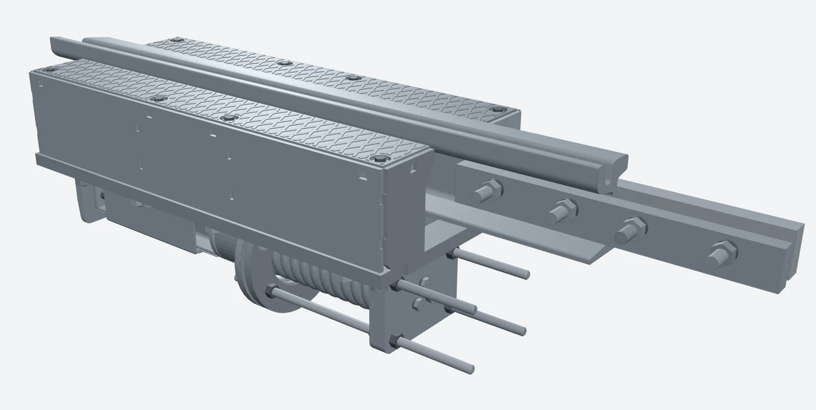
The agent reads an ESKD drawing in PDF or DWG and first writes every dimension into the model specification. If a view can be read two ways, it asks the design engineer before writing any code. The model is built in code with CadQuery, and the output is STEP for any CAD system.
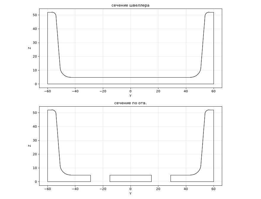
The agent's check isn't just words. A script compares the overall dimensions, volume and mass with the title block, builds sections and compares the shape with the reference using a boolean difference. If the mass doesn't match, we look for a mistake in how the drawing was read. Adjusting the density or a dimension to fit the answer is forbidden.
Design documentation to ESKD
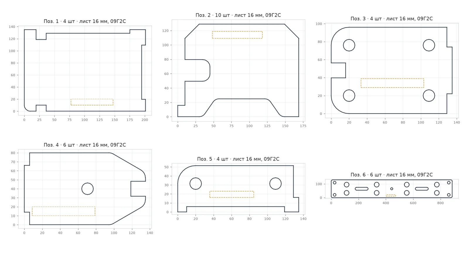
From the finished model the agent issues working drawings with a title block, bills of materials and a parts list. For laser cutting, a DXF of every sheet-metal part with marking: the item number is placed inside the contour, offset from the edge, clear of the holes.
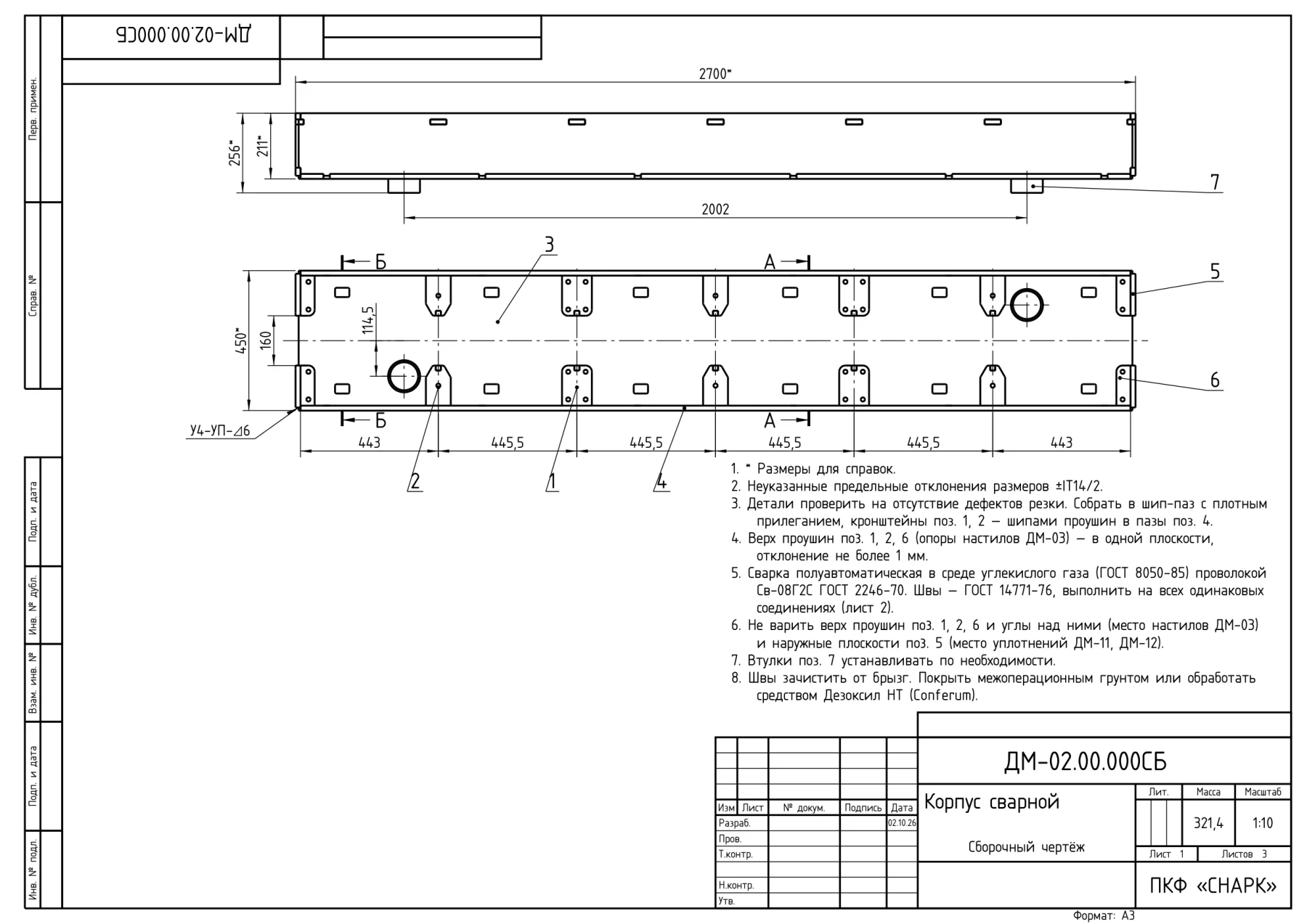
The parts list calculates mass and material grades and flags the places where a process engineer should take a look. Preparing the files and the cutting list used to take about three hours; now it takes about half an hour, including checking.
| Item | Qty | Dimensions, mm | Mass, kg | Agent's note |
|---|---|---|---|---|
| 1 | 4 | 201 × 135 × 16 | 3,2 | |
| 2 | 10 | 169 × 129 × 16 | 2,1 | |
| 3 | 4 | 135 × 96 × 16 | 1,5 | Ø13 holes are smaller than the sheet thickness: check the cutting mode. Marking 29 mm from the edge: closer than that, the holes get in the way |
| 4 | 6 | 135 × 80 × 16 | 1,2 | Ø13 hole is smaller than the sheet thickness: check the cutting mode |
| 5 | 4 | 135 × 51,5 × 16 | 0,7 | Marking in 7 mm font: 10 mm height doesn't fit |
| 6 | 6 | 886 × 129 × 16 | 12,7 |
Detailing a whole product with sub-assemblies and the general assembly now takes 3–4 hours instead of two weeks. The design engineer answers the agent's questions about interpretation and checks the result.
Engineering checks
We write checks for the task at hand: assemblability, clearances, masses, centre of gravity. The most visual one is the electrical insulation check of an assembly: the agent builds a contact graph of all parts and finds where current could reach the housing. You can rotate it in 3D on a separate page.
Rules for the agents
AI models make mistakes confidently. In one of the first runs the agent's report said all the windows in a part were in place, while they were shifted by almost 4 mm with the correct volume. So most of the work goes into a system in which such errors get caught on their own, rather than into prompts.
- Understand the drawing first, then build. Ambiguities go to the design engineer as a question before any code, and the answer is recorded in the task card.
- We don't take the report's word for it. The supervisor opens the model and checks the mass, sections and shape against the reference.
- Every run is recorded. A run log with scores on one scale, failed runs included. You can see which executor and which version of the rules produced the result.
- Every failure becomes a rule. The error is analysed and turned into a change to the method, a recipe or a tested function in the shared library. More than 40 such lessons already work as rules.
- Two loops. The supervisor and the executor are different agents. Some tasks can go to a local model on the design bureau's server, without sending drawings outside.
The rules, the function library and the log stay in the design bureau. A new design engineer or a new agent starts from the same point, not from scratch.
Who it's for
Design bureaus and engineering departments in mechanical engineering and steel structures. We start with one type of task, usually laser-cutting files, and teach the design engineers to work with agents. Then we expand to models and detailing.
Send us one set of drawings. We'll show what the agents do with it in a day and calculate how much time it would save your design bureau.